Series 6001 Radio Direction Finding System
The products for the series 6001 direction finders on this page are no longer in production. However, we do continue to support them with customer assistance and repairs. Contact the factory if you need help with any of these products.
The 6001 series radio direction finders provide microprocessor control for enhanced signal processing and remote control. These units are best for remote sites where multiple bearings are required for triangulation. We provide a Windows-based software with the unit. This permits lines of bearing to be displayed on a map in real time.
Features of the Series 6001 Direction Finders
- Broadband – 125 to 1000 MHz.
- All functions remotely controllable.
- Selectable commutation frequency for optimum match to signal conditions.
- 2 deg bearing accuracy (1 sigma, fixed site).
- Software for fast data acquisition from multiple sites and automatic triangulation to locate source on digital maps.
- Controllable signal averaging reduces multipath effects in mobile use.
- Front panel display of bearings in digital and compass rose format, and signal strength on scale of 0 to 9.
- Two data ports provide serial input and output in ASCII and CIV formats.
- Rugged, weather-resistant fixed site antennas include built in summer electronics and 8 elements.
- Notch filter eliminates commutation tone from audio output of built-in speaker.
The 6001 series is normally used at a fixed site as shown in the following block diagram. Note that the fixed site shown is local to the PC (if used). It may also be remotely located using various type of networks.
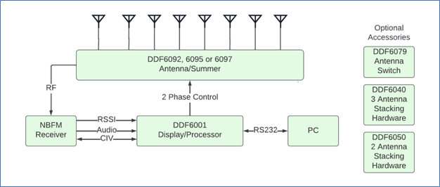
DDF6001 Display/Processor

The DDF6001 display/processor drives the RF summer with the waveforms required to mix the four antenna inputs smoothly and to produce the simulated Doppler modulation at the selected sweep frequency. Audio from the receiver is processed to calculate an estimate of the bearing angle. The DDF6001 may be used as a standalone fixed site without a PC. It may also be used as a homing radio direction finder (using the RF Summer and Antennas shown with the Series 5900). In addition, it can be used with the Bearing Track software. Typically, two to four remote fixed sites using DDF6001 processors are linked to a centralized PC to triangulate a signal.
Specifications of the DDF6001
- Type: simulated Doppler, 4 or 8 antenna elements. Selection of 4 or 8 element antenna summing is determined automatically at power turn-on.
- Commutation frequency: front panel selectable 300, 600, 1200 or 2400 Hz
- RF operating frequency: 125 to 1000 MHz
- Accuracy (in fixed site service) : 2 degrees error (one sigma)
- DF sensitivity: typically -130 dBm for CW
- Monitor speaker: built-in, with audio amplifier and notch filter to eliminate commutation tone, 0.5 W maximum output
- Sampling rate: best estimate calculated two times per second
- Averaging: over last 1, 2, 5, 10 or 20 bearings, front panel selectable
- Display/output: LED compass rose, plus 3-digit LED’s
- Serial interface: Two ports on rear panel. Port #1 is RS232 using ASCII or CIV protocol, port #2 is either RS232/ASCII or CIV bus. ASCII/CIV selection is determined automatically at power turn-on.
- RF attenuator: 24 dB, enabled from front panel
- Calibration: from front panel
- Audio input range: 0.01 to 0.6 VRMS
- Power requirements: 11 to 14 VDC, 1.0 Amp
- Operating temperature: 0 to 50 degrees C
- Dimensions: (HxWxD) 108x171x235mm (4.25×6.75×9.25 in)
- Weight: 1.9 kg (4.1 lb.)
- CE compliant
SignalTrack Software
This Windows based software program is supplied with the DDF6001. It provides real-time control and acquires bearing data from one or more remote direction finder sites. Remote site receiver frequencies may be changed, and all front panel direction finder controls are available. The software supports either Internet, data radio link, telephone line or direct (RS232) connection for control and data acquisition. When the direction finder connect over the Internet, multiple users can access the bearing data simultaneously. Bearing Track triangulates bearings automatically and displays lines of bearings on digital maps. A least squares estimation of the emitter location and/or the 95% probability ellipse can also be shown. SignalTrack includes data logging for offline analysis. For more details on this program, refer to SignalTrack.

DDF6092/6095/6097 Fixed Site Antennas
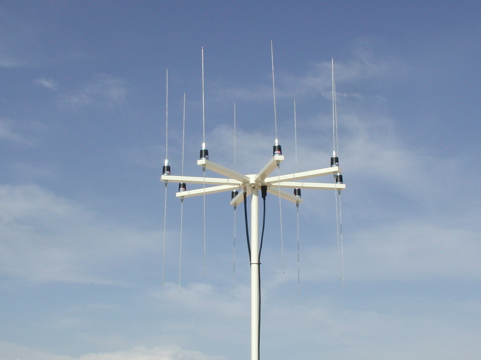
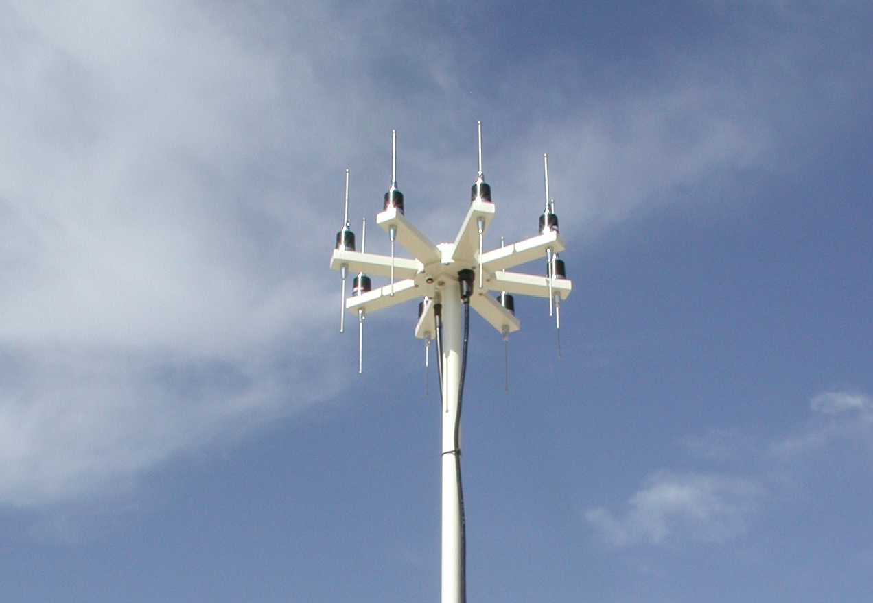
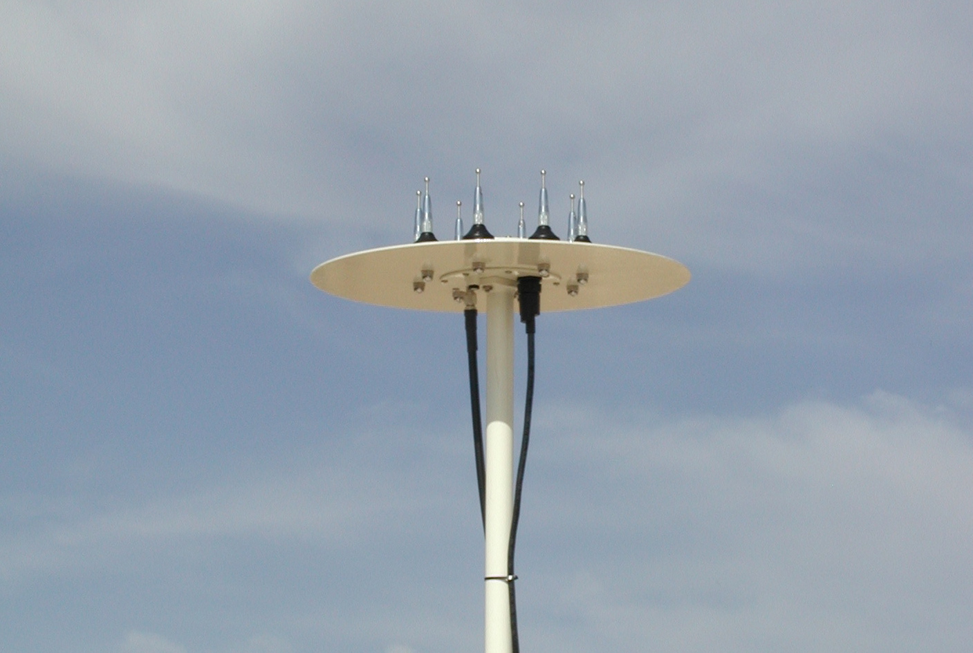
In short, these fixed site antennas contain the RF summing electronics in a sealed central hub. Elements are located at the end of eight arms connected to the hub. The antennas are shown mounted on the single mast adapter, DDF6216.
- Number of elements: eight
- Electronic summer: built into sealed hub assembly.
- Elevation/depression: operates at up to 45 degrees vertical angle of arrival.
- Wind speeds: resists speeds of up to 45 m/S (100mph).
- Materials and finishes: corrosion resistant throughout.
- Frequency range: the 3 models cover the range 125 to 1000 MHz.
- Center frequency and bandwidth: see table.
- Cable lengths available: any multiple of 7.6 m (25 ft) up to 91.5m (300 ft).
- Dimensions and weight: see table.
These antenna are normally provided with flexible whip-like elements that are tuned to the frequencies listed in the table below. If you desire to operate at a different center frequency, please specify it at the time of order.
| Model | 6092 | 6095 | 6097 |
| Frequency Range MHz | 125-250 | 250-500 | 500-1000 |
| Standard Center Frequency MHz | 150 | 450 | 860 |
| Bandwidth MHz | 25 (+/-12.5) | 100 (+/-50) | 150 (+/-75) |
| Array Diameter mm (in.) | 797 (31.37) | 403 (15.87) | 200 (7.87) |
| Element Length mm (in.) and type | 889 (35.0) Dipole | 305 (12.0) Dipole | 73 (2.87) Monopole |
| Weight kg (lb.) | 6.6 (14.5) | 3.5 (7.8) | 2.5 (5.6) |
DDF6050 Two Antenna Stacking Hardware
The DDF6050 permits stacking two fixed site antennas at a DDF6001 site. It can accomodate the following antenna pairs:
| Upper Antenna | DDF6097 | DDF6097 | DDF6095 |
| Lower Antenna | DDF6095 | DDF6092 | DDF6092 |
A heavy duty lower mast replaces the standard mast on the lower antenna. Coupling hardware and masts connect the lower antenna to the upper one. In addition, a vertical separation of 0.94 m (37.3 in.) is provided between the two antenna hubs.
DDF6040 Three Antenna Stacking Hardware

You may stack three fixed site antennas on a single mast using our hardware. You can stack the following antennas:
| Upper Antenna | DDF6097 |
| Middle Antenna | DDF6095 |
| Lower Antenna | DDF6092 |
A heavy duty lower mast replaces the standard mast on the lower antenna. Coupling hardware and masts connect the lower antenna to the middle one and the middle antenna to the upper one. In addition, a vertical separation of 0.94 m (37.3 in.) is provided between the lower and middle antenna hubs. The vertical separation is 0.46 m (18 in.) between the upper and middle antenna hubs.
DDF6079 Three Antenna Remote Switch

This switch connects to three fixed site antennas. You can use it to remotely switch both the control and the coax cables. You may also manually operate the DDF6079. LEDs show the switch status.
Additionally, the unit includes a 15 conductor control cable for connection to J8, a stereo cable for connection to J9 and a BNC-BNC coax cable for connection to the receiver. All cables are 1.8 m (6 ft) long.